

 |
 |
 |
 |
 |
 |
 |
 |
 |
![]()
![]()
![]()
This is a quick introduction of LectureLink by a PowerPoint Presentation.
An introduction of the software LectureLink.
|
MPEG1: 352 * 288 resolution with 25 frames/s MPEG2: 720 * 576 resolution with 50 frames/s Full TV resolution |
Ethernet or ATM TCP Chat & control channels UDP for A-V channels transmission |
|
MPEG audio Layer 2, Rate: 441kHz |
Control signal: 0% Chat signal: 0% A-V signal: one-way 1%, two-way 3% |
|
PowerPC 200 MHz CPU or higher 32 MB built-in memory (64 MB recommended) Butane II MPEG2 encoding card Mason X MPEG decoding card Color video camera with resolution 300 lines or higher Color TV monitor with A-V input |
Mac OS 8.5 or later QuickTime 3 or later A permanent IP address Total throughput: 0.4 - 10.0 Mb/s Communication latency: 1.0 - 1.7s |
Table of contents
|
|
|
|
|
|
|
|
|
|
|
|
|
This project, High quality multimedia delivery over IP networks which was developed by myself, is a subset of the Synchronous Distance Education System developed by New Zealand Educational Software Centre. It has developed a multimedia delivery system to support bi-directional high quality video, audio, chat messages and controls signalsdelivery over network in real-time. This software is based on Apple Macintosh system. To develop this system, there are four items have been considered: high quality video and audio, high data bit rate transmission, data loss and communication delay. For the delivery of live educational presentations, the video should be clear enough to precisely illustrate the concepts of the teaching, say full screen display or 720 * 576 pixels resolution. Then it needs a large amount of data throughput over the network to deliver essential video and audio information. To guarantee this transmission, a reliable network and its protocol are needed. Video transmission requires a huge data rate in the network and data loss is inevitable. To reduce data loss to a minimum is the one of the aims of this project. Picture compression will be used in this system. As the picture compression and decompression need time to be accomplished, so communication delay is unavoidable. Just like eliminate data loss, reducing compression delay is another important optimisation for this system. This system has been designed and implemented from scratch and has achieved following design goals:
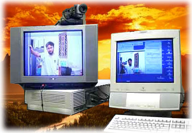
This system delivers lectures over Ethernet to the students’ end with fully-animated pictures and voices. Similarly, it also sends fully-animated pictures of the students and voices back to the lecturer’s end simultaneously. There are two streams for each one-way communication over the LAN. One is an MPEG multiplexed system stream (video and audio data), the other is the control stream, which conveys control signals and whiteboard data. The number of streams is doubled in bi-directional communication (See Figure 4-1 ). The following descriptions are assumed to be for the bi-directional communication. Figure 4-1 Streaming diagram The lecturer's audio and video streams are encoded by the MPEG encoder card and a multiplexed MPEG system stream is generated, which mixes the audio and video signals together with the time marks. Then that stream is divided into small packets and sent over the LAN using the UDP protocol. At the other end (the students' end), the packets are received and reassembled into the original MPEG system stream, assuming no packet loss, or something closely approximating it if there is packet loss. Then the stream is decoded into separate audio and video streams by the MPEG decoder card. The audio and video signals are fed directly to the display monitor. This exact procedure is also applicable to the students' end. So there are two channels that support this type of communication. The other two channels are used to exchange some essential control messages and allow remote configuration, such as adjustments to the display window's size and position. The control channel is also used as a whiteboard communication channel. Data can be directly sent to the network using TCP/IP protocol if its size is less than 64K. Otherwise it needs to be divided into small packets* . At the other end of the network, the control signal is received and corresponding activity is carried out. Figure 4-1 shows an example of the live communication between lecturer and students.
There are three components in this system. They are the Interface and control component that supports different windows, menus for settings and display of status, videos and chat messages, the Codec component that supports MPEG1 and MPEG2 encode and decode and the Network component that manages the network connections, transmissions and protocols (See Figure 4-2). Figure 4-2 Project components 3.1 Interface and control component This is the main control and interfacing component that supports human-computer communication and message display. It has seven modules:
Figure 4-3 Screen shot The Codec component performs MPEG encoding and decoding functions. There are two modules in this component, the Encoder and the Decoder.
This component serves as a network administrator, which controls the incoming client connection and creates related threads to communicate with the outside world. There are two modules in this component. They are Outgoing module, and Incoming module.
|

![]()
![]()
Designed by Yong Qiu Liu.
Copyright © 2006 All rights reserved