


![]()
Introduction of multimedia codecs
|
3.3 MPEG video |
|||||||||||||||||||||||||||||||||||
MPEG (Moving Picture Experts Group) is the ISO committee, which is responsible for defining the various MPEG video specifications. An MPEG video codec is used in many current multimedia products and is at the heart of many digital televisions set-top boxes, e.g. DSS, HDTV decoders, DVD players, video conferencing, Internet video, and other applications. It has a high compression ratio (up to 150:1) and needs less bandwidth for the transmission of the video stream over network and requires less space to store the encoded videos. Because of this, it has become an international standard. MPEG1 is the specification used for Video CDs and MPEG2 was intended for digital television applications and is used for DVD-Video. MPEG-4 is the latest standard and is intended for video conferencing. [63] [64] MPEG is derived from H.261 video standard and from the ITU and JPEG image formats. [65] It consists of two layers, a system layer containing timing information to synchronise video and audio and a compression layer including audio and video streams. MPEG-1 was originally optimised to work at video resolutions of 352 * 240 pixels at 30 fps (NTSC) or 352 * 288 pixels at 25 fps (PAL). The bit-rate is optimised for applications of around 1.5 Mb/sec.
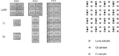
Research into the Human Visual System (HVS) has shown that the human eye is most sensitive to changes in luminance and less sensitive to variations in chrominance. To effectively take advantage of this, MPEG uses the Y (luminance), Cb (blue colour difference) and Cr (red colour difference) colour space to represent the data values instead of the RGB encoding normally used in computer graphics. When encoded, a picture frame can be divided into many macro-blocks that are 8 * 8 pixels in size. When referring to the YCbCr colour space, a macro-block can be represented in the formats of 4:4:4, 4:2:2 and 4:2:0 video. Here 4:4:4 is full bandwidth YCbCr video and each macroblock consists of 4 Y blocks, 4 Cb blocks, and 4 Cr blocks. 4:2:2 contains half as much chrominance information as 4:4:4, and 4:2:0 contains one quarter of the chrominance information. The 4:2:0 mode is the most widely used format in consumer level products, and it reduces the data required from 12 blocks/macroblock to 6 blocks/macroblock, that is a 2:1 compression compared to the 4:4:4 or RGB format. (Figure 2-11) [63] Figure 2-11 YcbCr format and pixel co-siting in 4:2:0[63]
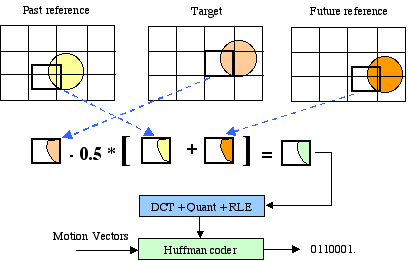
There are three types of frames in the MPEG format, I-frames, P-frames and B-frames. I-frames and P-frames are the same as in H.261. Whereas B-frames are coded as differences from the last or next I or P frames which are commonly referred to as bi-directional interpolated prediction frames (Figure 2-12).
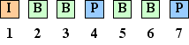
Figure 2-12 B-frames encode[65] Video Stream Composition For random access and the location of scene cuts in the video sequence, MPEG allows the encoder to choose the frequency and the location of I-frames. Normally I-frames are used two times a second. The number of B-frames between I or P frames can also be selected. The typical pattern of this sequence is 1 I-frame for every 12 to 15 frames. 2 B-frames between a pair of I or P-frams. A typical display order of frames is shown in figure 2.6. (Figure 2-13) Figure 2-13 Typical ordering of frames[62] For efficiency and to reduce latency, frames are re-ordered in the video stream to the decoder. The reference frames needed to reconstruct B-frames are sent before the associated B-frames. (Figure 2-14)
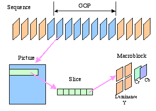
The structure of a MPEG video is described as sequence which is composed of a series of Groups of Pictures (GOP's). Furthermore, a GOP is composed of a sequence of pictures (frames). From higher level to lower micro level, the sequence of their subset is: [71] Sequence à GOP à Frame à Slice à Macro block à Y,Cb,Cr block or motion vector(Figure 2-15) Figure 2-15 MPEG hierarchical structure GOP (Group of Pictures): A GOP is an independent unit that can be decoded and can be of any size as long as it begins with an I-frame. It consists of all the frames that follow a GOP header before another GOP header. The first picture after the GOP header is an I frame that doesn't need any reference to any other picture. In its header there is a time code for the first picture of the GOP to be displayed. So this layer can be accessed randomly. Open GOP: Sometime a B frame, which follows an I frame after the header, has a reference that comes from the previous GOP. In this case the GOP is called an Open GOP. If a random access to such a GOP is performed, this B frame shouldn't be displayed. Closed GOP: when either there are no B frames immediately following the first I frame or such B frame haven't any references coming from the previous GOP, then this kind of GOP is called a Closed GOP. [72] Slice: A slice is a part of a MPEG image. There can be 1 slice per frame, 1 slice per macro-block, or anything in between. Each slice is coded independently from the other slices of the frame. This layer allows error confinement. If errors in the bit stream are detected, the decoder can try to continue the decoding process looking for the next slice header.[72]
Normally the adjacent pixels within an image tend to be highly correlated. MPEG encoding uses Discrete Cosine Transform (DCT) to reduce the data required to represent a single frame. Each of the 6 blocks (4 for Y one each for U an V) in the macro block is then decomposed into underlying spatial frequencies, which then allow further reducing of the precision of the DCT coefficients consistent with the Huffman coding. According to the Fourier transform, a signal is decomposed into the weighted sums of a series of orthogonal sines and cosines. When added together the original signal is reproduced. An 8x8 pixel block is converted to an 8x8 block of coefficients indicating a "weighting" value for each of the 64 orthogonal basis patterns (Figure 2-16) added together to produce the original image. Figure 2-17 shows how the vertical and horizontal frequencies are mapped into the 8x8 block pattern. [63] By missing the higher frequency components, the encoded data amount can be reduced again to reduce the bandwidth. Of course its quality will be degraded as well.
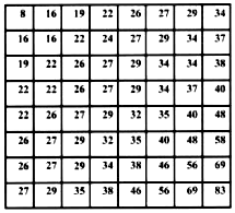
Figure 2-16 DCT basis patterns[63] Figure 2-17 Frequency map[63] DCT Coefficient Quantisation: Because the HVS is less sensitive to errors in high frequency coefficients than that in lower frequencies, the higher frequencies can be more coarsely quantised when encoding. In Figure 37 , the lower frequency DCT coefficients toward the upper left- corner of the coefficient matrix correspond to a solid luminance or colour value for the entire block. On the other hand, the higher frequency DCT coefficients toward the lower right corner of the coefficient matrix correspond to finer spatial patterns, or even noise within the image. Each coefficient is divided by a corresponding quantisation matrix value that is supplied from an intra quantisation matrix (Figure 2-18). It may substitute a new quantisation matrix at a picture level if the encoder decides it is warranted. This operation forces as many of the DCT coefficients to zero, or near zero, as possible to reduce the bandwidth required. [63]
Figure 2-18 default intra quantisation matrix[63]
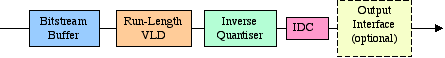
The decoding is performed in the reverse order of the encoding process. In this manner, an I frame decoder consists of an input bits-stream buffer, a Variable Length Decoder (VLD), an inverse quantiser, an Inverse Discrete Cosine Transform (IDCT), and an output interface to the required environment (computer hard drive, video frame buffer, etc.). ( Figure 2-19) Figure 2-19 Intra Frame Decoder[63] The VLD operates on a bit-wise basis to search every bit in the stream. Because of the extensive high-speed, bit-wise processing, it is more complex to implement than that in the encoder. The inverse quantiser multiplies the decoded coefficients by the corresponding values of the quantisation matrix and the quantisation scale factor. The resulting coefficients are clipped and an IDCT mismatch control is applied to prevent long term error propagation. At last the IDCT operation is completed. [63]
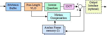
Non-intra decoding is similar to the intra-frame decoding except for the addition of motion compensation support. (Figure 2-20). Figure 2-20 Non-Intra Frame Decoder[63] The compression performance of MPEG 1 is shown in Table 2-3. Table 2-3 Compression performance of MPEG 1
MPEG-2 was designed with respect to digital television broadcasting, issues considered were the efficient coding of field-interlaced video and scalability. MPEG-2 is supports 720 * 480 resolution video at 30 fps (NTSC) and 720 * 576 at 25 fps (PAL), at bit-rates up to 15 Mbps. Another format is the HDTV resolution of 1920 * 1080 pixels at 30 fps at a bit-rate of up to 80 Mbps. Table 2-4 shows the parameters of normal MPEG2 applications on different levels: Table 2-4 MPEG-2 target applications
Differences between MPEG2 and MPEG-1
|


![]()
![]()
Designed by Yong Qiu Liu.
Copyright © 2006 All rights reserved